Table of Contents
Photocells / Light Dependent Resistors (LDR)
Lecture Slides
About LDR
 |
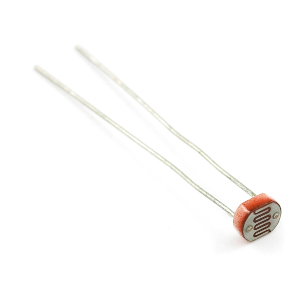
| Fig.: A cadmium sulfide (CdS) photocell. (Source: SparkFun) |
“The cadmium sulfide (CdS) or light dependent resistor (LDR) whose resistance is inversly dependent
on the amount of light falling on it, is known by many names including the photo resistor, photoresistor,
photoconductor, photoconductive cell, or simply the photocell.”
(cited from Cadmium sulfide (CdS) or light dependent resistors (LDR), by Token, a company from Taiwan)
A common series of LDRs is A9060-XX. The model A9060-09 is often used.
Sample datasheets by PerkinElmer are:
Large Variance among specimen of the same product series
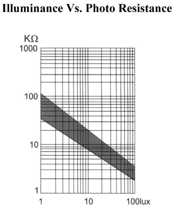
The GL5528 datasheet from Sparkfun illustrates the broad performance variety between LDR of the same type:
LUX
The light “intensity” illuminating the photocell is measured in Lux. This unit takes not just the physical light quantity but also the sensitivity of the human eye into account. It combines physics with physiology.
“The lux (symbol: lx) is the unit of illuminance, or luminous flux per unit area, in the International System of Units (SI). It is equal to one lumen per square metre. In photometry, this is used as a measure of the intensity, as perceived by the human eye, of light that hits or passes through a surface. It is analogous to the radiometric unit watt per square metre, but with the power at each wavelength weighted according to the luminosity function, a standardized model of human visual brightness perception. In English, “lux” is used as both the singular and plural form.” (from Wikipedia)
High Performance Variability
Do not trust the resistance-vs-lux curves too much. Adafruit states on its tutorial on Photocells for Arduino:
“Each photocell sensor will act a little differently than the other, even if they are from the same batch. The variations can be really large, 50% or higher! For this reason, they shouldn't be used to try to determine precise light levels in lux or millicandela. Instead, you can expect to only be able to determine basic light changes.”
(cited from Arduino related tutorial on Photocells, by Adafruit)
 |
| Fig.: Typical performance variation of photocells of the same type (log-log-plot). (Source: GL 5528 Photodetector by SparkFun) |
The datasheet on GL5528 Photocell by SparkFun reflects these uncertainties.
LDR Voltage Divider Experiment with Arduino
Arduino Code: ADC to Serial
- LDR_V001.ino
/*
 * Voltage divider with LDR
 *
 * Circuit:
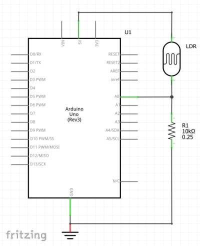
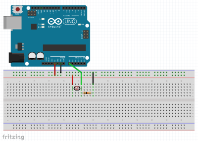
 * 5V (Vcc) - LDR - R1 - GND
 * The node between LDR and R1 (V1, voltage drop across R1) is connected to analog input A0
 * R1 arbitrary, e.g. 10kOhms
 *
 * The voltage V1 is converted to a digital number (dn) by means of an analog-to-digital converter (ADC).
 * The range of dn: 0 <= dn <= 1023 (10 bit resolution)
 *
 * Conversion:
 * V1 = 0V -> dn = 0
 * V1 = 5V -> dn = 1023
 *
 * Reconstruction of voltage from digital number:
 * V = dn / 1023 * 5V
 *
 */

int AIN = A0; // Analog input pin number

void setup() {
  // put your setup code here, to run once:
  Serial.begin(115200);
  Serial.println("dn  V  mV");
}

void loop() {
  // put your main code here, to run repeatedly:

  int  dn = analogRead(AIN); // digital integer number between 0 and 1023 (10 bits, 2^10 different values)
  float V = (float)dn / 1024 * 5.0; // convert dn to float first, then divide by 1024
  int  mV = V*1000; // millivolts, converted from float

  Serial.print(dn);    // print to serial without a newline at the end, i.e. the next print is in the same line
  Serial.print("  ");  // spaces
  Serial.print(V);
  Serial.print("  ");
  Serial.println(mV);  // last print with newline, i.e. the next print will be in the next line.

  delay(100); // pause in ms, 100 ms means 10 meas / sec.
}


