
Table of Contents
Notes on Seeeduino Boards
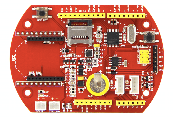
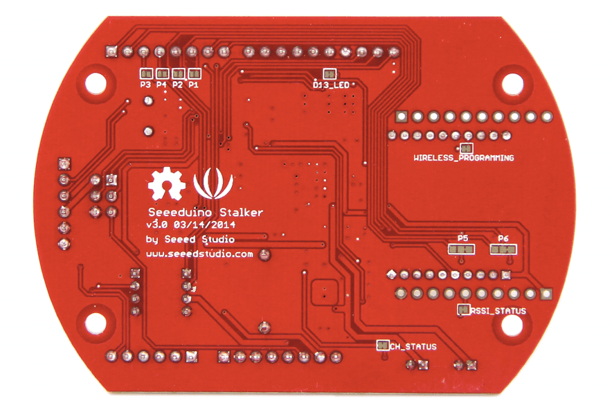
Seeeduino Stalker v3
Power Down, RTC Interrupt and Tipping Bucket Rain Gauge
Some of you are using Seeeduino Stalker V3 boards.The main source of information is the wiki:
http://www.seeedstudio.com/wiki/Seeeduino-Stalker_v3
The most efficient way to save power is to make the Arduino sleep deeply with set_sleep_mode(SLEEP_MODE_PWR_DOWN); sleep_enable();
The problem is that in SLEEP_MODE_PWR_DOWN only external interrupts INT0 (at pin D2) and INT1 (at pin D3) can be used to wake the system up again (pin change interrupts could also be used). Internal timers as well as serial communication are switched off and cannot be used to wake the system up. The onboard realtime clock (RTC) can do the job.
The RTC provides two alarm signals (hardware lines INTA and INTB) of which you just need INTA. You have to close a solder jumper (by soldering the right adjacent pads together) to connect INTA (of RTC) to INT0 (pin D2 of MC ATmega328, or - in Arduino notation - pin 2 of Arduino), see
http://www.seeedstudio.com/wiki/Seeeduino-Stalker_v3#PCB_Jumper_Pads
The onboard realtime clock is a DS1337 and can be programmed using a library (modified DS1337 lib) you find here: http://www.seeedstudio.com/wiki/File:DS1337.zip
Now the DS1337 has to be programmed such that it will issue a logic 0 at INTA if an alarm occurs (low active). As described above this signal is connected to INT0 and would wake up the microcontroller. You can program the RTC e.g. to raise an alarm (interrupt) every minute.
The other interrupt INT1 can be used to count the tipping events of a tipping bucket rain gauge some of you are using.
The algorithm for the tipping bucket is as follows:
- Initialize the system,
- initialize count = 0 (counts the tipping events, measure of small water volume)
- Print a welcome message
- Sleep
- If a tipping event occurs (INT0) wake up, increment count (count++) and sleep again (step 4)
- If a RTC alarm occurs wake up, get real time, print count (and/or store it on SD), reset count = 0 and sleep again (step 4)
The variable count counts the number of tipping events. The tipping occurs when a certain amount of rain has been accumulated in the little buckets. Thus it counts small volumes of rain water.
The count - water volume relationship can be calibrated e.g. by pouring known volumes of water into the funnel of the tipping bucket rain gauge and counting the tipping events. This calibration experiment is repeated several times and for several different volumes. The result is the relationship between counts and volume (e.g. liters, cm³, m³, mm³).
After a predefined period (recurring interval, e.g. one minute) the accumulated counts are registered together with the time stamp either on SDcard or printed.
The final result is the rain intensity or more precisely volumetric flow rate (e.g. in mm³/min) over time.
Sample Code
This UNTESTED CODE  includes
- Power down
- RTC interrupt (INT0)
- Tipping bucket rain gauge reed switch interrupt (INT1)
- SDcard file I/O
- RF-Bee via soft UART, library softserial
Wireless Data Transmission with RF-Bee
You can transfer data between two RF-Bees, i.e. one on the Stalker (or another Arduino), the other at the receiving gateway (server, PC, Raspberry PI, …).
The other (non wireless) side of the RF-Bees communicate via UART with the device they are wired with.
The idea:
- Arduino sends data to RF-Bee 1 via wires (UART)
- RF-Bee 1 sends data to RF-Bee 2 over the air
- RF-Bee 2 sends data to its host (Raspberry PI or anything else) via wires (UART)
The small Arduinos based on ATmege328 (Arduino Uno, Seeeduino Stalker, ,…) just have one UART which by default is used for the USB connection, e.g. when using something like Serial.print(“Hello”);
The workaround is a so-called soft-UART, (library softserial.h), an emulated UART in software. The performance of a soft UART is limited, but it can help to connect another UART device such as RF-Bee to the Arduino.
To use the RF-Bee module with Seeeduino Stalker V3 you have to connect the RF-Bee RXD and TXD signals to the two digital pins D6 and D7, respectively:
- solder jumper P6: BEE_TXD → D6 (soft UART RX),
- solder jumper P5: BEE_RXD ← D7 (soft UART TX) (attention: HW bug of Stalker V3),
as described here: http://www.seeedstudio.com/wiki/Seeeduino-Stalker_v3#PCB_Jumper_Pads
There are two bugs concerning the connection of any Bee module to the Stalker pins to use software serial. The following connections have to be established to use the Bee module with a software serial port (UART emulated in software, library softserial.h):
- solder jumper P6: BEE_TXD → D6 (soft UART RX),
- solder jumper P5: BEE_RXD ← D7 (soft UART TX)
Hardware Bug
There are two hardware bugs on Seeeduino Stalker V3 related to solder jumpers P6 (BEE_TXD) and P5 (BEE_RXD). Because of that just closing the solder jumpers as described here will not work!
The official workaround only solving part of the problem is given here:
http://www.seeedstudio.com/wiki/Seeeduino-Stalker_v3#Known_Issue
To solve both issues I propose a solution described in the following document:
stalker_v3.0_workaround_p5_p6_2016-06-21_v002_rb.pdf
RF-Bee Configuration
to be done