
Table of Contents
Dragino LoRa Components
DLOS8 4G
Outdoor gateway with 4G modem.
http://www.dragino.com/downloads/index.php?dir=LoRa_Gateway/DLOS8/
LSN50 v2

Fig.: LSN50-V2 WATERPROOF LORA SENSOR NODE (Antratek)
A list of all relevant documentation:
- LSN50 Documentation Collection from the Dragino Download Server
LSE01 Soil Sensor Kit
The LSE01 sensor kit consists of a LSN50 v2 LoRaWAN node plus a soil sensor providing soil moisture, soil temperature as well as soil electrical conductivity. Unfortunately the LSE01 software to communicate with the soil sensor as well as the soil sensor itself are closed source. It is totally unclear how the sensor works. It is not specified and not even the brand is known.

Fig.: LSE01 LORAWAN SOIL SENSOR (Antratek)
A list of all relevant documentation:
- LSE01 Documentation Collection from the Dragino Download Server
- LSE01 AT Commands v1.0 (pdf)

Shopping
State of 2021-01-04:
LSE01/LSN50 Device Registration in a The Things Network Application
A84041B2A18264AC
A840416151829000
The procedure is also described in the LSE01 manual v1.4.
Any LoRaWAN device has to be registered (“paired”) with a TTN application. Preferably over the air activation (OTAA) is used. In the case of OTAA the following information has to be transferred from the preset LoRaWAN device to the TTN application.
| LoRaWAN Device | Direction | TTN Application | Description |
|---|---|---|---|
| APPEUI | ⇒ | App EUI | Application EUI, unique application ID |
| APPKEY | ⇒ | App Key | Application Key for message encryption |
| DEVEUI | ⇒ | Device EUI | Device EUI, unique device ID |
DEVEUI, APPEUI and APPKEY are preset in the Dragino LoRaWAN devices. They can be read and modified by means of AT commands. The easiest way to read the parameters from the device is to issue the command AT+CFG to retrieve all configuration parameters. The three parameters can also be taken from stickers attached to the LSE01/LSN50 device as well as a sticker on the paper box of the device.
Create a new application on the TTN console to collect all the data from the sensor nodes. An application can have several different App EUIs each of which being capable to serve as an unique application identifier for a registered device. Additional App EUIs can be created an manually filled in. The APPEUI suggested by the device to be registered has to be added to the list of the TTN App EUIs.
The problem with this method is that that you have individual App EUIs for each device connected. The advantage is that the device does not have to be opened and configured via a serial interface. It is also easier to bind the device to another application without changing/programming the device.
When the TTN application is created successfully it allows to register devices. Each device has a unique Device EUI. This can be taken from the LSE01/LSN50 settings and filled in into the respective field during device registration.
Furthermore an App Key has to be set in TTN which is shared between device and application to encrypt the data transmission on application level. Each device can have its own App Key or the devices share the same key. Fill in the APPKEY from the device into the respective field during TTN device registration.
Create a new application on your TTN console and click on register new device.
Insert the Device EUI of the Dragino sensor node (to be found on the sticker on your device or retrieved by AT+CFG).
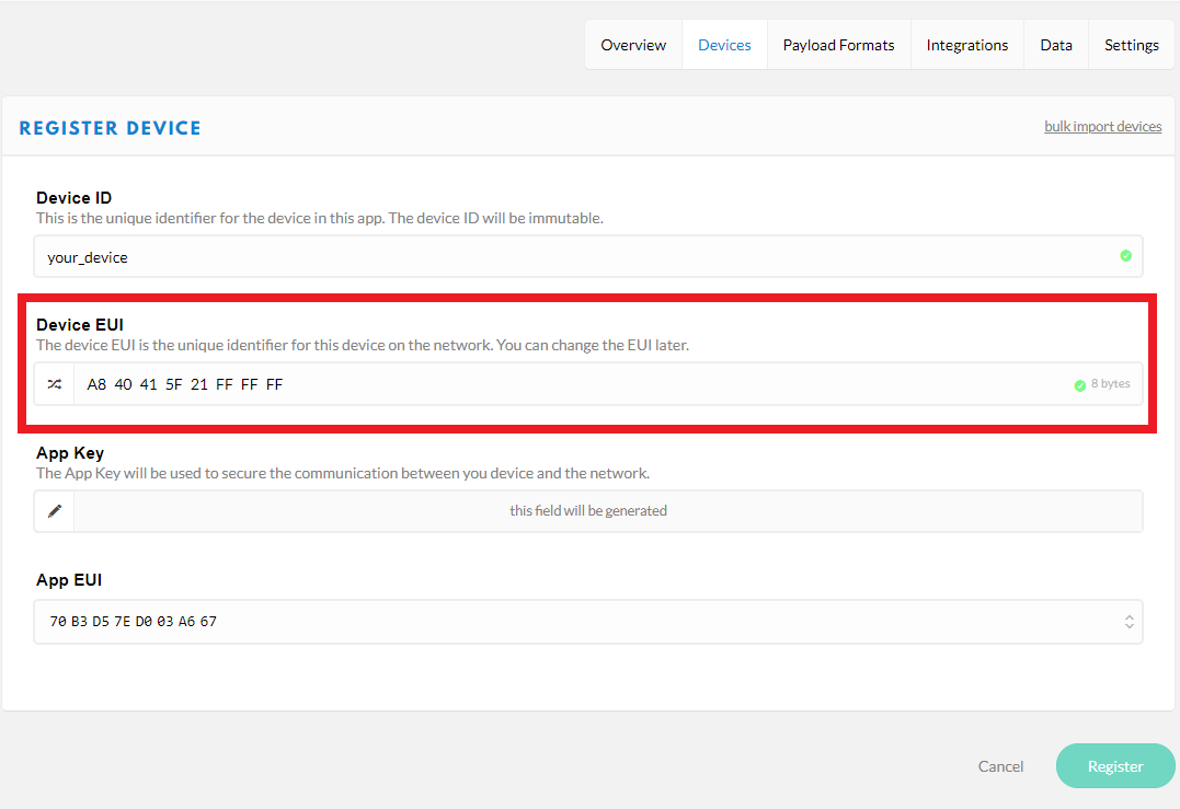
TTN will generate an App Key and an App EUI. Additional App EUIs can be added under settings. An individual App Key per registered device can be set during device registration.
Setting and Getting Configuration Parameters of LSE01/LSN50
In some cases it may be reasonable to change parameters in the LoRaWAN nodes, e.g. so that all devices are configured to use the same APPEUI and APPKEY. It also may make sense to change the time interval for taking measurements depending on the application.
The configuration is done by means of a serial terminal (e.g. putty, realterm, hterm, etc.) and a USB-to-Serial Converter connected to the microcontroller board. The available commands follow an extended AT modem command set.
Connecting USB-to-Serial
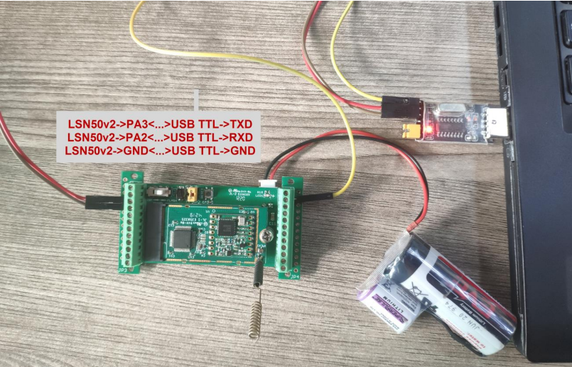
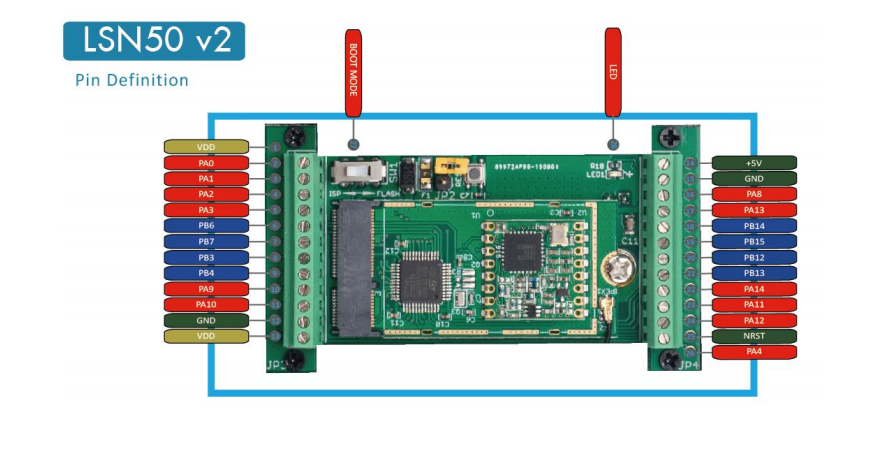
You have to open the enclosure and connect a USB-to-Serial Converter to the microcontroller pins PA2 and PA3 as well as ground. The USB-to_Serial-converter should work on 3.3V logic.
According the datasheet https://www.st.com/resource/en/datasheet/stm32l051c6.pdf the MC pins PA2 and PA3 are 5V tolerant but you would better use a 3.3V converter.
| Microcontroller Pin | USB-to-Serial Converter Pin |
|---|---|
| PA2 (USART2_TX, 5V tolerant) | RX |
| PA3 (USART2_RX, 5V tolerant) | TX |
| GND | GND |
 |
| Fig.: A USB-to-Serial Converter (here UARTSBee by Seeedstudio) connected to LSE01. |
Power up the Dragino node by setting the yellow jumper.
Connect it to your computer and open a serial terminal (for example Putty or RealTerm).
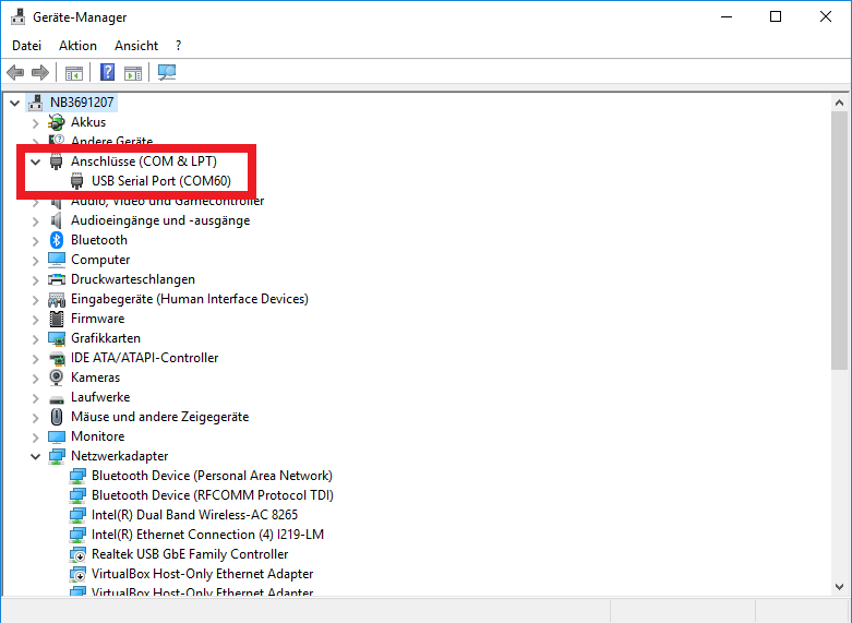
Open the windows device manager to check on which com port the USB ttl converter has connected
Open the com port with your terminal (baud rate: 9600).
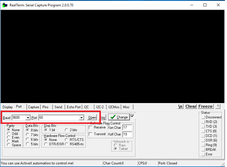
Send the following command to your device:
AT+CFG
If everything went well you will get a response with the current configuration of your device.
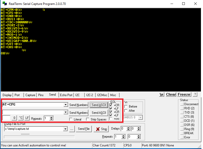
To connect to your TTN application you will need to set the App Key and App EUI with the following commands:
AT+APPEUI=<yourappeui>
and
AT+APPKEY=<yourappkey>
Example:
AT+APPEUI=70 B3 D5 7E D0 03 A6 67
AT+APPEUI=?                                                  //get current App EUI

AT+APPKEY=1C 8D FF DB D6 73 B5 43 00 9A E6 1D 3D C6 08 6A
AT+APPKEY=?                                                  //get current App Key
You should get an “ok” response if your command was accepted.
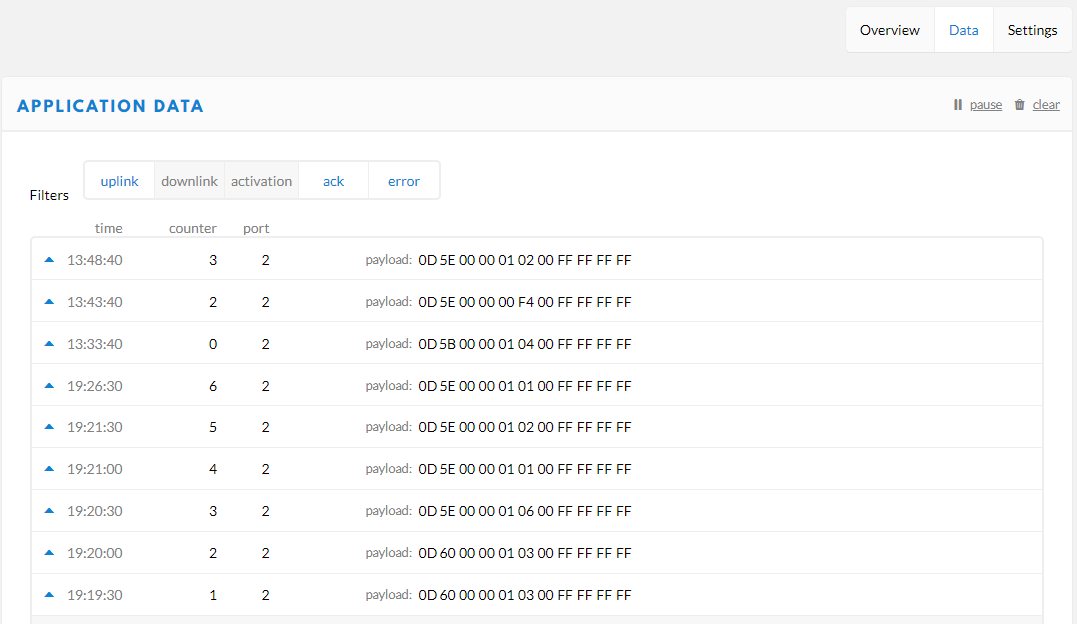
Go to your TTN application and check if the device connected:
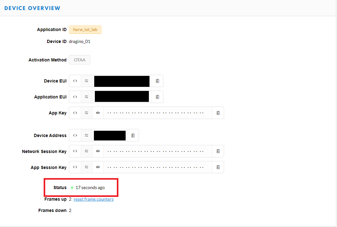
By default the dragino node will send the battery voltage as the first two bytes of the payload
You can change the transmit interval with the following command:
AT+TDC=30000 //time in ms
Dragino has a set of extended AT command e.g. for setting the LoRa parameters. Have a look at the official
List of AT-Commands on the Dragino Wiki.
Please refer to the manual to see how you can change the mode and connect a sensor:
LSN50 LoRaWAN Sensor Node User Manual, Document Version: 1.7.1
Soil Moisture, Temperature & EC Sensor
It is unclear which soil sensor is used for LSE01 kit. The sensor as well as the LSE01 firmware are closed source. The sensor has an orange sticker with several tick mark fields for different interface and power options. This may help to identify it.
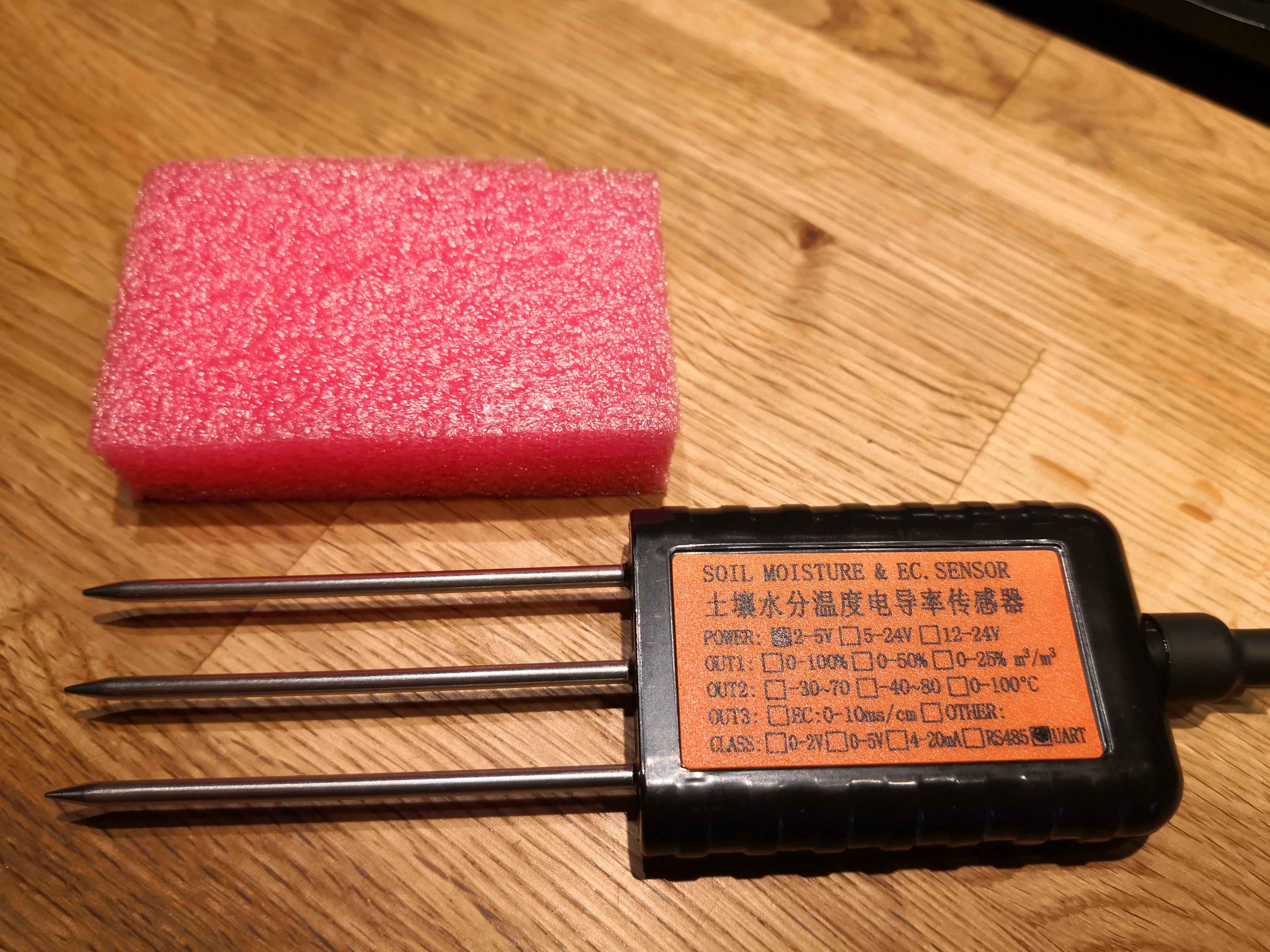 |  |
| Fig.: The soil sensor of the LSE01 | Fig.: A picture from the internet. |
Some product pages to be analyzed further:
- Chinese, but with MODBUS protocol description: https://www.aliexpress.com/item/4000249441083.html
- Chinese, but with MODBUS protocol description: https://www.aliexpress.com/item/1005001332617508.html
LoRa-Lite-Gateway (IMST iC880 + Raspberry PI)
Wifi Configuration
How to Compile the Dragino STM32 LoRa Firmware
The firmware of Dragino LSN50 is compiled with Keil Compiler Suite.
Chapter 5 (p. 54 ff) of the LSN50_LoRa_Sensor_Node_UserManual_v1.7.1 lists all the links to the necessary information.
Firmware Source Code
KEIL Firmware Compile Instructions
Hardware Design Flies
Pre-Compiled HEX File for LSN50
The pre-compiled hex codes for LSN50 can be found here:
https://www.dragino.com/downloads/index.php?dir=LSN50-LoRaST/Firmware/LSN50.hex/